Description
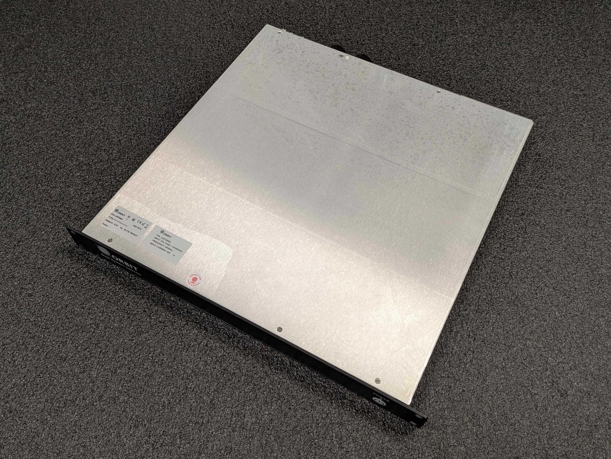
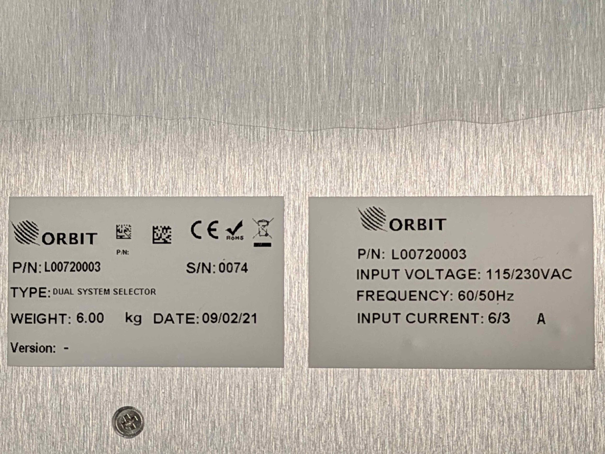
The DSS is used to implement the dual-system configurations. Both ADEs are managed via the CCU. The DSS provides interfaces to the following:
-
- Second Antenna unit interface
- IF RX and TX connection to satellite modem
The DSS front panel contains the On/Off switch.
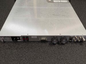
The DSS rear panel contains the power interfaces, and connections to the CCU and second antenna unit (ADE).
DSS Rear panel Interfaces:
-
- ADE2: N-Type. Connects to the ADE-BDE coaxial cable on the second system
- CCU – RX: F-Type. Input, connects to the CCU RX port
- CCU – TX: F-Type. Output, connects to the CCU TX port
- MODEM – RX: F-Type. Output, connects to the CFE modem RX port
- MODEM – TX: F-Type. Input, connects to the CFE modem TX port in systems with a CCU without 10MHz and to the CCU AUX-IF2 port with a CCU with 10MHz
- LAN: R-J45. Connects to one of the CCU LAN ports
- AUX COM: D-Type. 15-pin – passes the switching commands from CCU to the DSS. Connects to the CCU AUX COM port
- POWER: Connects to the mains AC power
- POWER: Turns the power to the internal DSS power supply ON or OFF
- ATTN – 1: Raises or lowers attenuation of the first system (attached to the CCU) Tx signal in 1dB steps
- ATTN – 2: Raises or lowers attenuation of the second system (attached to the DSS) Tx signal in 1dB steps
- ATTENUATION – 2 RX: Turns Rx attenuation of the second system ON or OFF (8dB Attenuation)
- ATTENUATION – 2 TX: Turns Tx attenuation of the
